
Convair Electronics :: Convair Electronics Crossovers & Components :: Convair Electronics Crossover PCBs
 |
| |||||
|
| ||||||||||||

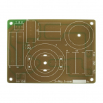
Convair Electronics PCB9013 For 2-way Crossover
Crossover PCB designed for a range of 2 way passive crossovers with attenuation on the high-pass section.
Dimensions: 160 x 120mm
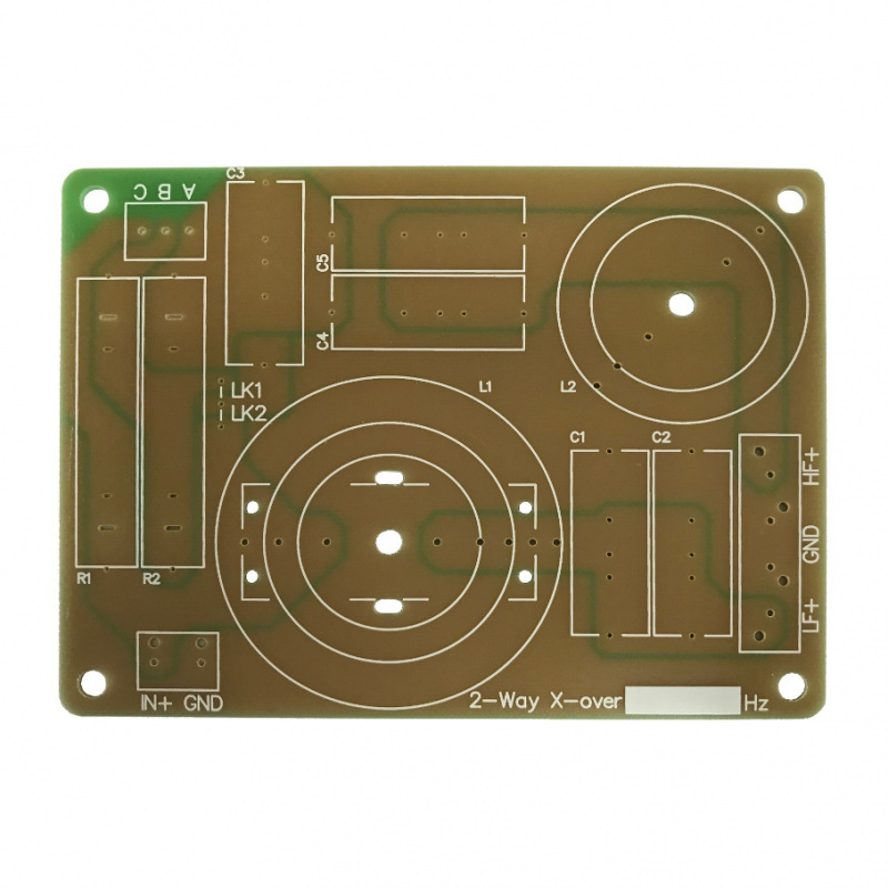
For standard symmetrical butterworth filters, the component values will be the same for both high pass and low pass sections.
L1 is the low pass inductor, and will usually be physically larger as it will handle more power than the high pass inductor.
L2 is the high pass inductor, and in higher power / high quality applications it is preferable to use an air cored inductor to reduce distortion.
C1 and C2 are for the low pass capacitor(s) - two spaces are provided so that capacitors can be arranged in parallel to achieve the desired value. e.g. for 4.4uF it would be preferable to use 2 x 2.2uF capacitors instead of 1 x 4.7uF capacitor.
C4 and C5 are for the high pass capacitor(s) - two spaces are provided for arranging capacitors in parallel.
Need some help calculating values? Why not try our crossover calculator: Crossover Calculator
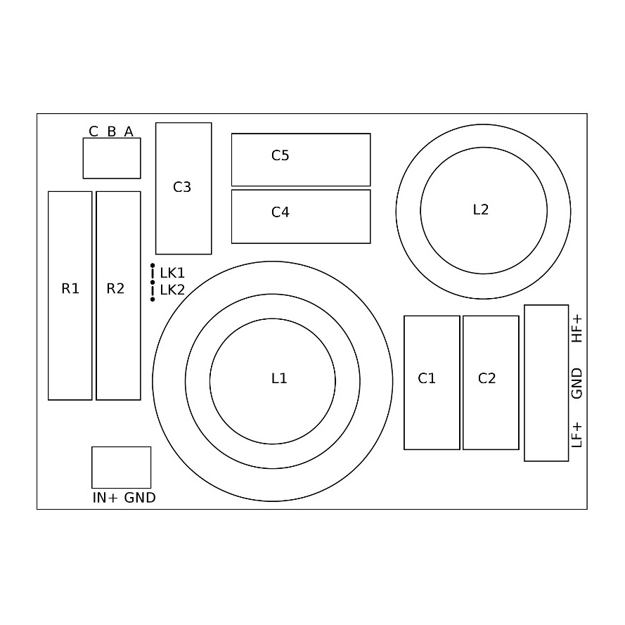
Select the filter type, frequency and driver impedances and then click the upper 'CALC' button to get the values you need for your crossover. The results will give a value for C1 (created using C1, C2 and C3 on the board) and C2 (created using C4 and C5 on the board). L1 and L2 will be as designated on the PCB.
The PCB has the high pass and low pass marked with standard + and - connections. It is very common to connect the Tweeter (High Pass) in reverse phase on a butterworth crossover as this will often give a more uniform response across the crossover point. It is worth trying both normal phase and reverse phase to see which works best in your system.
Dimensions: 160 x 120mm
For standard symmetrical butterworth filters, the component values will be the same for both high pass and low pass sections.
L1 is the low pass inductor, and will usually be physically larger as it will handle more power than the high pass inductor.
L2 is the high pass inductor, and in higher power / high quality applications it is preferable to use an air cored inductor to reduce distortion.
C1 and C2 are for the low pass capacitor(s) - two spaces are provided so that capacitors can be arranged in parallel to achieve the desired value. e.g. for 4.4uF it would be preferable to use 2 x 2.2uF capacitors instead of 1 x 4.7uF capacitor.
C4 and C5 are for the high pass capacitor(s) - two spaces are provided for arranging capacitors in parallel.
Need some help calculating values? Why not try our crossover calculator: Crossover Calculator
Select the filter type, frequency and driver impedances and then click the upper 'CALC' button to get the values you need for your crossover. The results will give a value for C1 (created using C1, C2 and C3 on the board) and C2 (created using C4 and C5 on the board). L1 and L2 will be as designated on the PCB.
The PCB has the high pass and low pass marked with standard + and - connections. It is very common to connect the Tweeter (High Pass) in reverse phase on a butterworth crossover as this will often give a more uniform response across the crossover point. It is worth trying both normal phase and reverse phase to see which works best in your system.
This product has been discontinued - please do not try to order this item we will not be able to supply it - the product details are here for reference only. Please contact a member of staff, and we may be able to find an equivalent product for you.
Detailed specifications unavailable, please EMAIL the sales office for additional information.
| Other Convair Electronics products similar to Convair Electronics PCB9013 For 2-way Crossover: |
|
||


|

|